

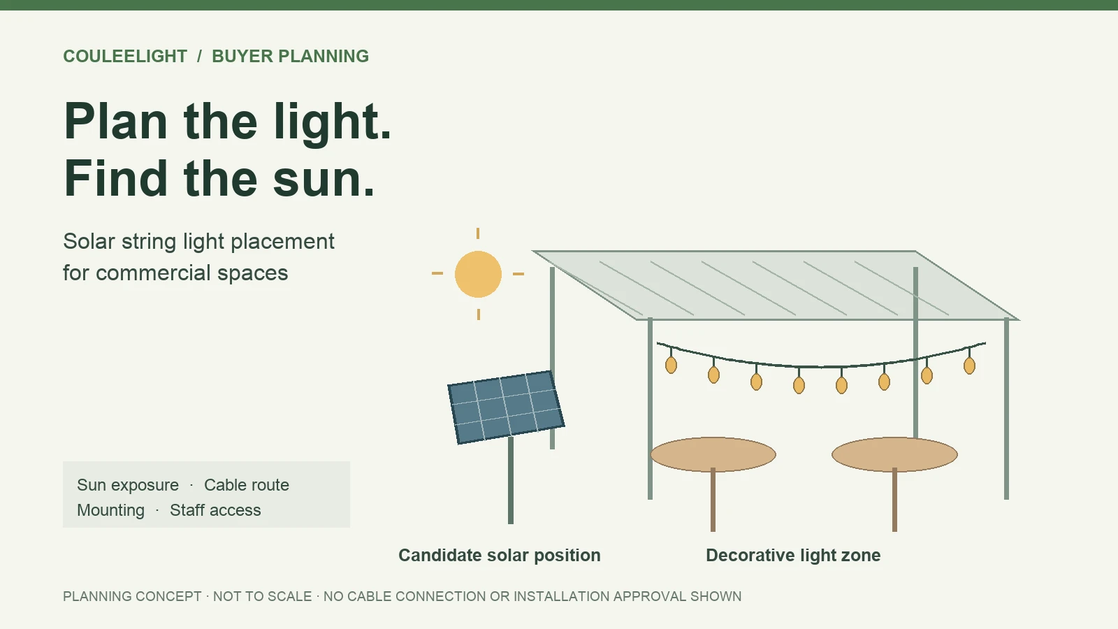
A restaurant terrace may need its lights beneath a pergola while the best solar exposure is beyond the roof. Before choosing a set, establish whether its supplied cable and approved mounting arrangement can connect those two needs. A longer advertised string is useful only if the unlit section reaches the first required bulb position.
Plan three things together: the decorative light zone, a viable solar position and a permitted route between them. Then check how staff will reach the controls and how the installation will be supported. This guide turns that site information into a configuration request for importers, brand buyers and hospitality projects; it does not provide an installation approval.
On this page: System arrangement · Solar position · Cable route · Fixings and access · Site check · Enquiry brief
Identify what can actually move
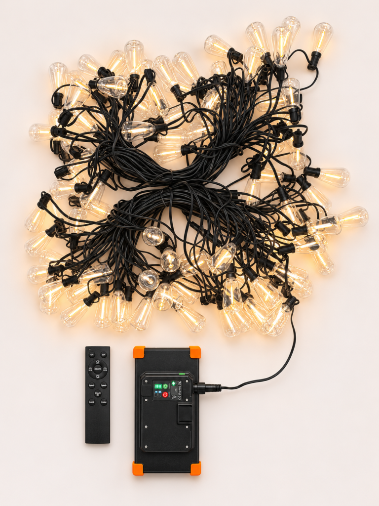
The solar panel, battery and controls may share one housing. In that arrangement, moving the panel also moves the controls and the string connection. A system with a separate panel and control box has a different constraint: both the panel-to-box cable and the box-to-string cable must reach their destinations. Do not draw them as independently movable components until the supplier confirms the actual assembly.
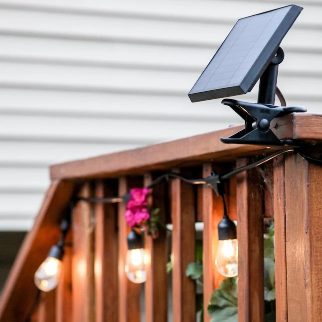
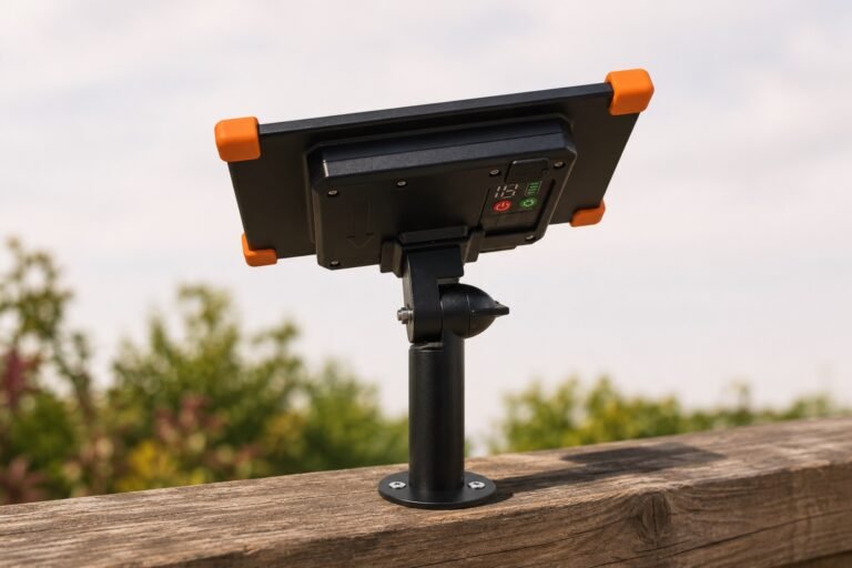
Couleelight’s supplied CLS-001 S14 user manual describes a solar panel with a built-in battery, with controls and a USB-C charging port on its back. It shows wall, ground-stake and deck-clamp arrangements. These are instructions for that documented model, rather than a mounting menu for every Couleelight set. Match the current manual and supplied accessories to the exact version being quoted.
For a shaded dining area, begin with two or more possible positions for the solar assembly. Mark the required first light point separately. If no permitted cable route reaches from a suitable solar position, revise the layout, consider separately supplied sets, or request a different documented system. Do not solve the mismatch by assuming that the panel can be detached from its housing.
Solar position candidates
A · Roof edge
Record shade through the day; check safe access and fixing suitability.
B · Terrace boundary
Record nearby trees, guest access and the longer route to the lights.
Decorative light zone
C · Beneath the pergola
Mark the first and last required bulbs, each run and clearance constraints.
The place that looks right after dark may be shaded during charging.
Include vertical changes and turns. Compare that route with the supplied unlit cable and any expressly approved extension.
Assess solar access for the season you intend to use
A panel can look unobstructed at lunchtime and spend much of the useful charging period behind an awning, tree or adjacent building. The Australian Government’s solar design guidance (opens in a new tab) explains that shading changes with an obstruction’s position and height, the time of day and the season. Its rooftop guidance supports the solar-access principle; it does not predict a small lighting kit’s charging performance.
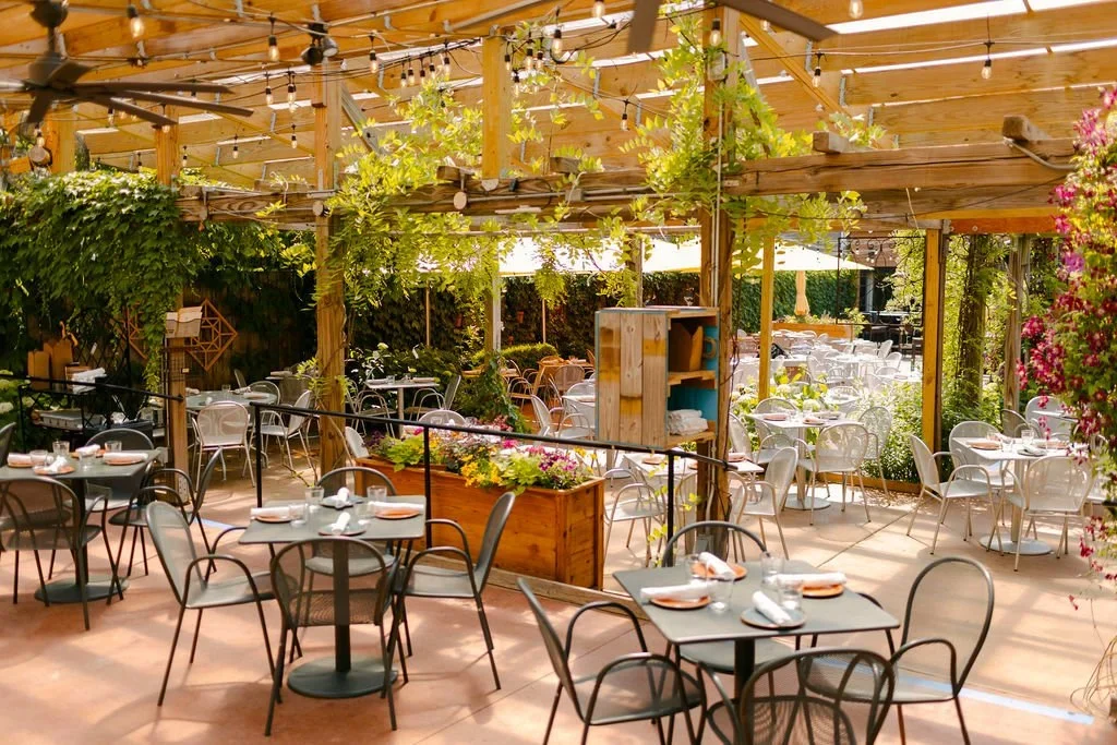
For each candidate position, take photographs from the intended panel location at several times through a representative day. Date and label them, note the local time and weather, and show movable awnings, parasols and nearby foliage. A photograph records that moment; use a local sun-path assessment where other operating months may produce different shadows. Include planned construction or vegetation growth if it could change exposure.
Record the direction the panel would face and its tilt from horizontal. A direction that works in one region is not a global instruction: US solar assessments commonly consider south-facing exposure, while Australian guidance discusses north-facing roofs. The DOE/PNNL site-assessment guide also treats orientation, tilt and shading as separate inputs. Have the proposed position assessed for the actual latitude, obstructions and operating season, particularly in tropical or unusual site conditions.
The US Department of Energy’s solar radiation explanation identifies location, time, season, landscape and weather as factors in the resource available. Hours of daylight alone therefore do not establish daily recharge. Give the supplier your required nightly operating window and brightness or mode, alongside the site record, and request a stated basis for its charging assessment. A clear summer day cannot establish winter service.
Check the reach to the first bulb, not just total length
Measure along the proposed cable route, including the rise to the mounting point and turns around the structure. Keep the unlit approach to the first bulb separate from the decorative run. A straight line on a floor plan can miss both the vertical distance and a detour needed to avoid a doorway or guest route.
| Length to identify | What the supplier’s drawing should show |
|---|---|
| Panel-to-box cable, if separate | Each endpoint, supplied length and whether separation is permitted. Not applicable where the components share one housing. |
| Unlit approach to the string | The output reference or connector through to the first bulb, showing each supplied cable section. |
| Illuminated section | First and last light positions, measurement convention, operating bulb count and spacing. |
| End tail and total length | Tail after the final bulb and the exact components included in the advertised total. |
| Any proposed extension | Part reference, permitted interface, added length and approved complete configuration. |
For example, a hypothetical route that rises 2 m and then travels 3 m along a beam already needs 5 m of unlit reach before allowing for the actual turns and permitted installation detail. A set advertised as 12 m long could still be unsuitable if its first bulb arrives too soon. These figures illustrate route measurement, not a Couleelight specification or a recommended allowance.
Measure the route to the first light point
upCorner3 m along beamFirst light point
(first bulb)
2 m + 3 m = 5 m of unlit reach
These two segments total 5 m, before allowing for the actual turns and permitted installation detail.
The supplied CLS-001 manual lists a 100 cm USB-C cable, but does not dimension the lighting lead or identify an approved extension. That USB cable length cannot answer the placement question. Request a dimensioned cable drawing and written extension decision for the quoted version.
Extensions are system-specific. As a separate manufacturer example, Festive Lights describes its CG044B extension as a 5 m accessory for its ConnectGo range. That identifies an accessory within its own system; it is no evidence of compatibility with Couleelight. For your proposed build, obtain the supplier’s approval of the connector pair, electrical loading, cable length and outdoor-use arrangement. Similar-looking plugs do not establish a match.
If the proposed reach is outside the approved arrangement, return to the site plan before requesting a bulk price. Moving the solar assembly, changing the first light position or using separate sets may be more practical than pursuing an unsupported extension. Keep any alternative configuration and its price separate in the quotation.
Resolve fixings, support and staff access together
A good solar position still needs a suitable fixing surface and a workable operating position. Record whether the proposed attachment is masonry, timber, a railing or another structure, together with its condition and relevant dimensions. Ask which supplied fixing arrangement applies and what the installer must provide. A clamp shown in a manual does not establish suitability for every railing profile, surface or wind exposure.
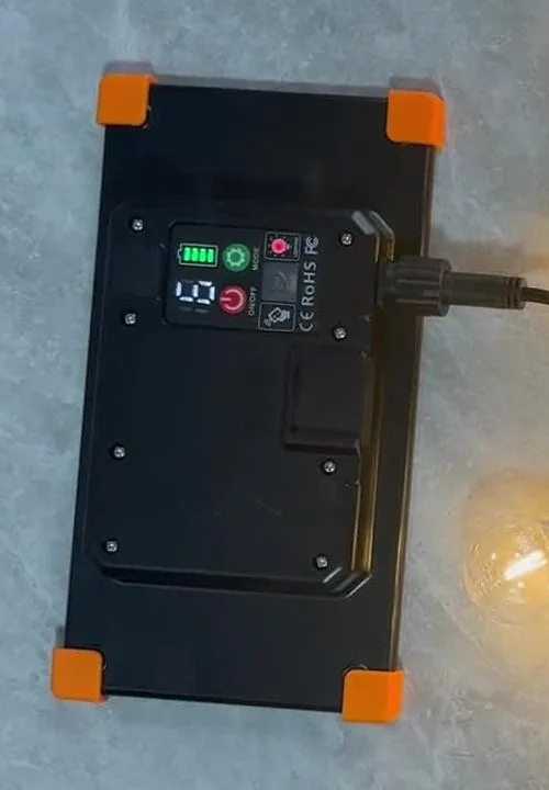
With an integrated solar assembly, a high mounting position may improve exposure while making the rear buttons, status display or charging port awkward to reach. Plan for the operations the actual model requires: switching off, reading indicators, cleaning the panel and, where supported, auxiliary charging. Keep that access compatible with guest areas and the manufacturer’s port-cover and environmental instructions. Do not presume a remote replaces every physical operation.
The light string needs its own support assessment. Obtain the permitted attachment points and hardware, limits on unsupported spans, any required support wire, and the intended drape and clearances. Have the responsible installer confirm the structure, fixings and exposure for the site. Do not use the electrical cable or a mated connector as an assumed tension member, and do not prescribe a universal fixing interval or sag allowance.
The supplied CLS-001 instructions prohibit securing wiring with staples or nails and hanging extra objects on the string. Apply the matching manual’s restrictions and ask the supplier to resolve any proposed installation detail it does not cover. Keep cables clear of pinching, sharp edges and routes where people or equipment could catch them. Site-specific installation and any applicable local requirements remain for the responsible installer to confirm.
Check the proposed positions by day and after dark
Before committing to the bulk configuration, review an identified sample in the proposed arrangement where practicable, after the supplier and installer have cleared it for that use. Record the sample version, drawing revision and any departures from the plan. This is a recommended check, not a claim that the configuration has already been tested.
- By day: compare the supplied cable sections with the measured route; check the panel’s actual shade, permitted tilt, fixings, cable protection and access to controls. Photograph the final proposed positions.
- After dark: assess the decorative result from seated and standing positions; check interference from venue lighting with any dusk-sensing function, and verify the actual operations staff will need.
- At handover: retain the agreed positions, component and accessory references, instructions and open restrictions. If the solar position, route or string configuration changes, ask which approvals and checks must be revisited.
The CLS-001 troubleshooting section specifically notes that light from bulbs, streetlights or another source reaching the panel can cause night-time switching problems. Check that condition with the venue’s normal lights operating, rather than relocating or masking a sensor without the manufacturer’s instructions. The result of one evening does not verify repeated daily solar recovery.
Decorative approval is separate from the lighting needed for circulation, steps, working areas or emergency use. Have the venue’s responsible adviser assess those requirements for the site. A pleasing string-light scene does not establish that the space meets them.
Send a site brief the supplier can quote against
Copy the following text into an email or project document and fill it in there. Attach a marked sketch and dated photographs; unknown fields can remain open for the supplier’s response. This page does not accept or save entries.
Solar string light site and configuration brief
Project and use
Buyer / project reference:
Destination country and site location or region:
Application, intended operating months and estimated quantity:
Required nightly operating window, brightness / mode and separate task or safety lighting provision:
Solar position candidates
Candidate A / B references on the sketch:
Direction and tilt at each position:
Dated photos / observation times / weather / shade and seasonal concerns:
Nearby artificial lights, foliage, awnings and planned changes:
Route, mounting and access
First and last required bulb positions / each decorative run:
Measured route from each solar candidate, including vertical changes and turns:
Fixing surfaces and dimensions / existing supports / clearance and guest-access constraints:
Access for buttons, indicators, cleaning, isolation and any supported charging:
Requested supplier response
Proposed model, version and integrated or separate component arrangement:
Dimensioned drawing: panel-to-box cable if applicable, unlit approach, illuminated section, spacing, end tail and total:
Approved extension or connection decision, named parts and complete configuration limits:
Permitted mounting and string-support method / supplied versus installer-provided hardware:
Charging assessment basis for the stated location, season and operating requirement:
Applicable instructions and outdoor-use documentation / site questions still open:
Price basis, sample proposal and any exceptions to our brief:
For a brand or importer serving several destinations, keep one configuration reference per intended use and state the regions and seasons the instructions must cover. Avoid turning a successful demonstration at one site into a general “works anywhere” promise. Ask the supplier to identify which requirements it can meet and which need a revised layout or configuration.
Discuss your site plan with Couleelight
Send Couleelight your target market, estimated quantity, a marked route sketch and photographs of the proposed solar positions. Include the operating months and required evening schedule so the discussion can focus on the configuration that may suit the site and the information still needed before quotation approval.
For broader range and order planning, see the G40 wholesale buying guide. Confirm the exact configuration and installation documentation for this project separately.


[…] the wider assessment of solar exposure, controls access and commercial-site constraints, read commercial placement guide (opens in a new tab). For range selection and wholesale order planning, use the G40 wholesale buying guide (opens in a […]
[…] cable reach and mounting, use the commercial placement guide. The G40 runtime section explains why starting charge and settings matter, and the USB-C backup […]