

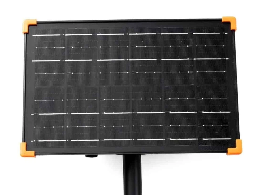
A matching plug and voltage label do not prove compatibility. Before ordering, match the string’s required drive, its load under the intended conditions, and its connector and control interface to a specific control-box model and variant.
For importers, lighting brands and OEM buyers with an existing string, this guide sets out what to collect, what to ask the supplier and what to record before approving a configuration.
Start with the string and identify every interface
Collect the light-string model and revision, its original supply or controller label, manual, layout and connector photographs. Record the operating bulb count, lamp type, illuminated length, lead length and any extensions or branches. A spare bulb in the carton is not an operating load. G40, ST38, S14 and S11 describe appearance; they do not identify the required electrical supply.
Then identify the proposed control-box model, output variant and relevant hardware or firmware revision. Establish which functions sit inside the box and which remain in the string. Some strings contain their own current-control electronics; others depend on an external driver. Replacing that driver with a superficially similar supply can change how the LEDs are driven.
Keep four specifications separate: solar-panel input, battery nominal voltage, auxiliary charging input and lighting output. A USB power-bank output, where fitted, is a further interface. None can stand in for the lighting-output specification. Integrated housings may hide some of these boundaries; the supplier’s documentation should still identify them.
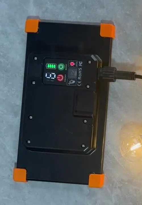
Concept only · identify the boundaries in your actual system
- Solar panel → charging section
Record panel requirements at the charging input. - Battery ↔ charging and power circuitry
Record the battery specification separately. - Output driver → string connector → light string
Match the lighting drive and the complete interface.
Auxiliary charging, if fitted, enters its documented charging interface. Parts may share one housing. This is a functional map, not a wiring diagram or a Couleelight model drawing.
Match the drive before comparing voltage
Couleelight’s solar control-box output options include 3V, 24V and 31V. Select the specific model and output variant against the string’s requirements: availability of a voltage option does not establish a verified box–string pairing.
Begin with the actual output type at the lighting interface. Establish whether the string requires steady DC, pulsed DC, AC or a polarity-reversing drive. Obtain the waveform, frequency and voltage definition where relevant. A nominal voltage without these details leaves the comparison incomplete.
Constant voltage (CV) holds a specified voltage within stated conditions; the compatible string must have the current control it needs. Constant current (CC) regulates LED current while the output voltage varies within a permitted operating window. For a CC string, match both its required current and its forward-voltage range to that window. MEAN WELL distinguishes direct LED drive from supplying lamps with driver electronics in its LED power-supply selection guidance, Q3 (new tab).
PWM switches an output on and off to control its average delivery. It does not by itself tell you whether the underlying system is CV or CC. Also distinguish PWM applied to the lighting output from a PWM control signal entering a driver. MEAN WELL’s LED catalogue, printed page 21 (new tab) identifies a CV PWM-output family with separate dimming connections; this is an illustration of the distinction, not a solar-box recommendation.
Request the permitted voltage range at the string, output tolerance, ripple or pulse amplitude where relevant, and operating conditions. Multi-channel, colour-changing or addressable strings also need the correct channel arrangement or control protocol. A single-colour string and an RGB string can share a voltage label while requiring different interfaces.
Check the load at the rating’s actual boundary
Ask what the quoted maximum covers: the complete box, each channel, one port, or a named string configuration. If several channels can operate together, obtain their individual limits and the combined limit. A permitted LED count applies to the specified LED and wiring arrangement; it is not a universal bulb allowance.
For a steady DC CV load, P = V × I is useful when voltage and current describe the same operating point and measurement boundary. Compare the whole-string demand with both the available current and power limits. For CC drive, the required current and operating voltage window remain essential even when the wattage appears acceptable.
With PWM or other varying waveforms, average power is the average of the instantaneous voltage–current product. Multiplying two basic meter readings need not give that result. Ask a competent supplier or laboratory for a method suited to the actual waveform, including peak or on-state demands and per-channel loading where relevant. An unloaded output-voltage reading cannot establish operation with the proposed string. The measurement principle is explained in Teledyne LeCroy’s guide to instantaneous and average power (new tab).
Lamp count multiplied by labelled lamp watts is only a preliminary estimate unless those figures represent actual input consumption and the full circuit boundary is known. LED-chip power and “equivalent wattage” are unsuitable substitutes for complete-string input data. Extensions and branches also need a cable-current and voltage-drop assessment; insufficient voltage at the far end can alter operation. MEAN WELL discusses cable rating and load-side voltage drop in its general FAQ, Q1 (new tab).
Obtain the load rating’s brightness, mode, supply or battery operating range, temperature and installation conditions. Include start-up behaviour, permitted minimum load if any, thermal derating and any restriction on simultaneous lighting and charging. A reduced average draw in a flashing mode does not establish that peak demands are acceptable. Use the manufacturer’s stated allowance or agreed engineering assessment; there is no universal spare-capacity percentage for every solar box.
Compare the connector pair, pin map and control logic
A photograph helps identify the connector family and visible damage. It cannot prove its internal wiring. Request a drawing or part reference for both mating halves, including housing dimensions, pin count and spacing, keying, insertion depth, lock or thread, and the specified seal arrangement. Check the cable specification and connector current and voltage ratings for the intended conditions.
The pin map must name each contact and specify the drawing’s viewing direction: looking into the mating face is different from looking from the cable side. Confirm polarity for fixed-polarity DC, or the documented channel and polarity-switching arrangement for other outputs. Never assign positive and negative from connector shape or wire colour alone.
Bulgin’s 400 Series wiring and assembly instructions (new tab) separately identify contact layouts, cable-side views and sealing components. They show why a connector needs more than a pin count; their dimensions and ratings are not specifications for a Couleelight connection.
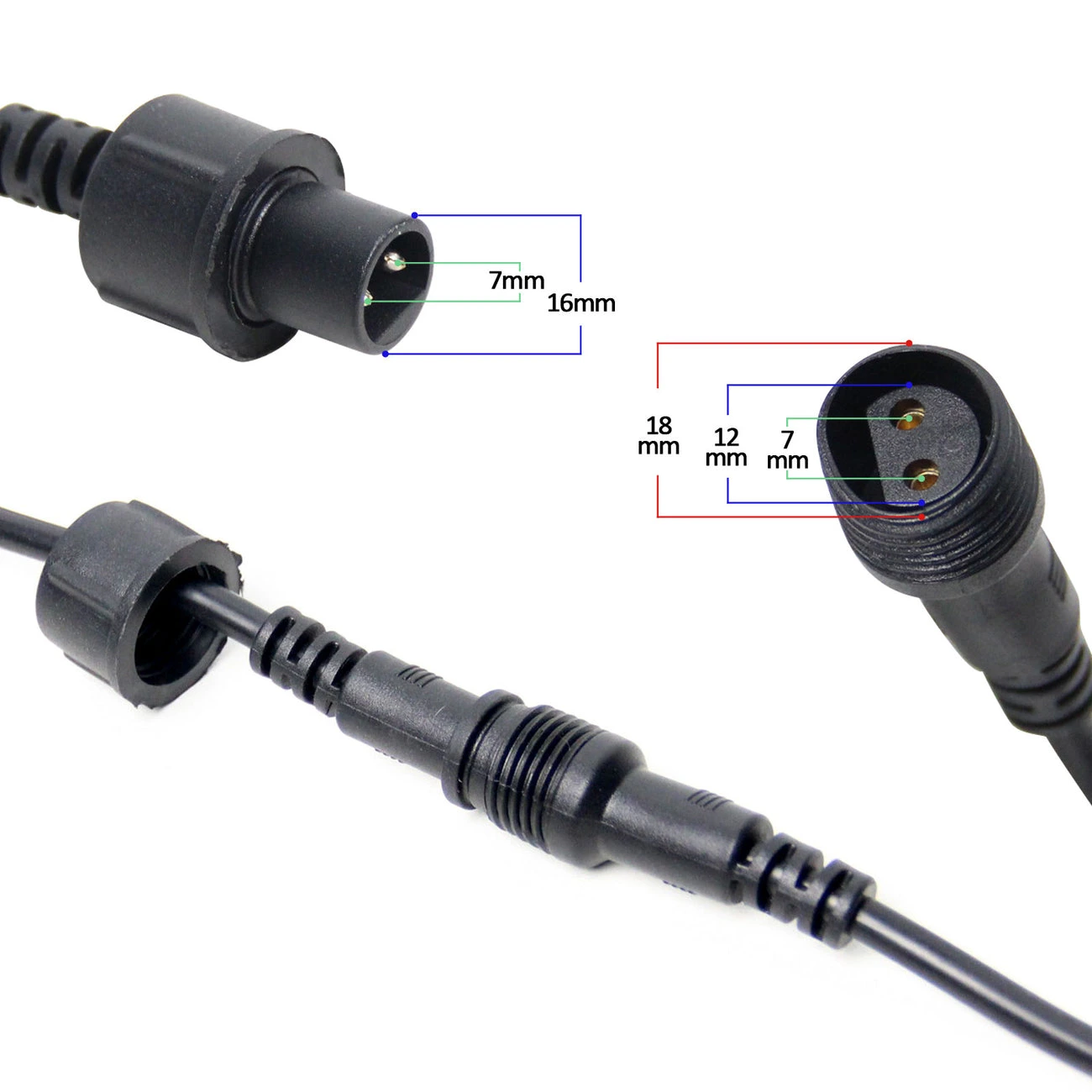
Next establish how the box creates the requested lighting effect. Does it switch supply polarity, modulate separate channels, send data, or control electronics inside the string? Where applicable, confirm common positive or common negative, signal levels, protocol and compatible firmware. A plug can mate correctly while these arrangements disagree.
Specify only the control behaviour relevant to this pairing: supported dimming method and range, stable operation in the required modes, channel response and restart state. A remote that operates the box does not establish that the connected string receives a suitable drive.
Build an approval record for the exact configuration
Keep supplied information, unresolved questions and approval evidence in separate columns. Use the blank worksheet below for a real proposed pairing. Add document references and revisions as they arrive; a blank field means no evidence has been recorded, not that the check has passed.
Copy this blank worksheet into your own document to record the proposed configuration. This page is not an online form.
| Check | Information supplied | Still to confirm | Approval evidence / reference |
|---|---|---|---|
| Box and string IDs / revisions | |||
| Drive, voltage range and current | |||
| Whole-system and channel load limits / conditions | |||
| Connector pair, pin map and polarity or channels | |||
| Dimming / control interface | |||
| Exact-pair verification and permitted use |
Written specifications allow the supplier’s engineer to assess a proposed match. If the supplier says the pair has been tested, request a record identifying the box and string, component revisions, method, settings, conditions, acceptance limits and result. Ask the supplier to explain whether its statement rests on drawings, calculations, an existing verified configuration or a test of your proposed pair. These are different forms of evidence.
Proposed approval sequence
- Collect the identified string and box documents.
- Resolve drive, load and interface discrepancies.
- Review evidence for the exact pair and intended conditions.
- Record the approved configuration, limits and revisions.
If a required limit, pin map or drive requirement is missing, hold configuration approval and request that specific information.
A buyer’s ordinary sample review can confirm visible identity and documented user operation after the combination has been cleared for that use. It does not replace electrical assessment. Do not trial-connect an unknown combination, open a sealed box, short contacts or alter wiring to find out whether it works. Unresolved technical questions belong with the responsible supplier or qualified laboratory.
Electrical matching is one part of order approval. Nightly endurance, daily solar recovery, bulk consistency and complete-system outdoor protection need their own evidence.
Recheck the match when the configuration changes
A longer lead may change voltage drop without adding lamps. More bulbs, a different lamp type or a revised series/parallel layout can change the required current, voltage window and channel balance. A new dimming method or firmware revision can change the waveform, start-up sequence or control interface.
For each change, return to the affected drive and load limits, cable assessment, connector pin map and control requirements. Have the supplier identify which existing evidence still applies and which assessment or verification must be repeated. Also revisit endurance and protection evidence where the change affects them. Record whether the revised build remains within the approved configuration.
Send a supplier a focused matching brief
Use the following brief for an initial enquiry. Attach what you have and leave unknown technical fields blank; ask the supplier to identify the missing information before recommending a configuration.
Copy the brief into your enquiry and complete the fields you know.
Subject: Solar control-box matching enquiry — existing light string
Light-string model / revision:
Original supply or controller label and manual attached:
Lamp type, operating quantity and string layout:
Illuminated length / lead length / extensions:
Known drive, voltage and load data with source:
Connector photographs of both sides and any drawing:
Proposed control-box model / variant, if selected:
Required dimming, modes and channel behaviour:
Application, destination market and operating conditions:
Expected quantity and sample requirement:
Please identify a proposed box–string configuration and provide its lighting-output specification, total and per-channel load limits with conditions, mating-connector drawing and pin map, and supported control interface. State the basis of your compatibility assessment, any exact-pair verification available, outstanding information and the next step needed for configuration approval.
For broader order planning, see our wholesale guide to MOQ, samples and lead times (new tab).
Discuss your existing string with Couleelight
Send your light-string information, proposed control-box model, connector photographs and application requirements. Couleelight can review the proposed configuration with you and identify the information needed to move the enquiry forward.

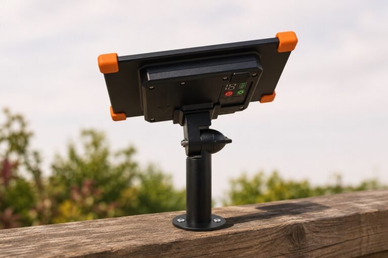

[…] For string length, bulb count and trial-order planning, see the G40 wholesale buying guide. For the separate lighting-output checks, see how to match a solar control box to your string lights. […]